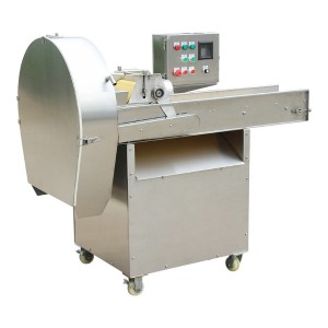
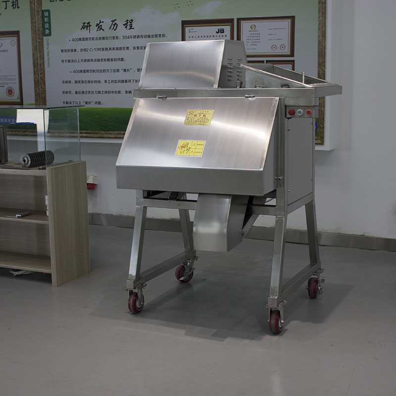
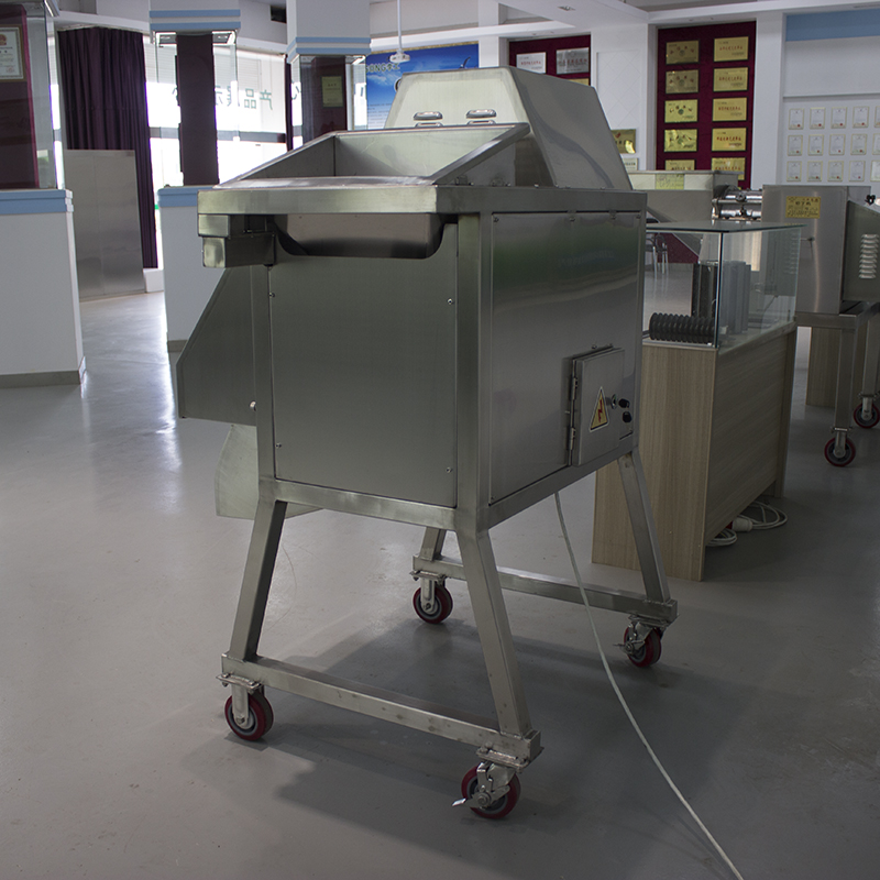
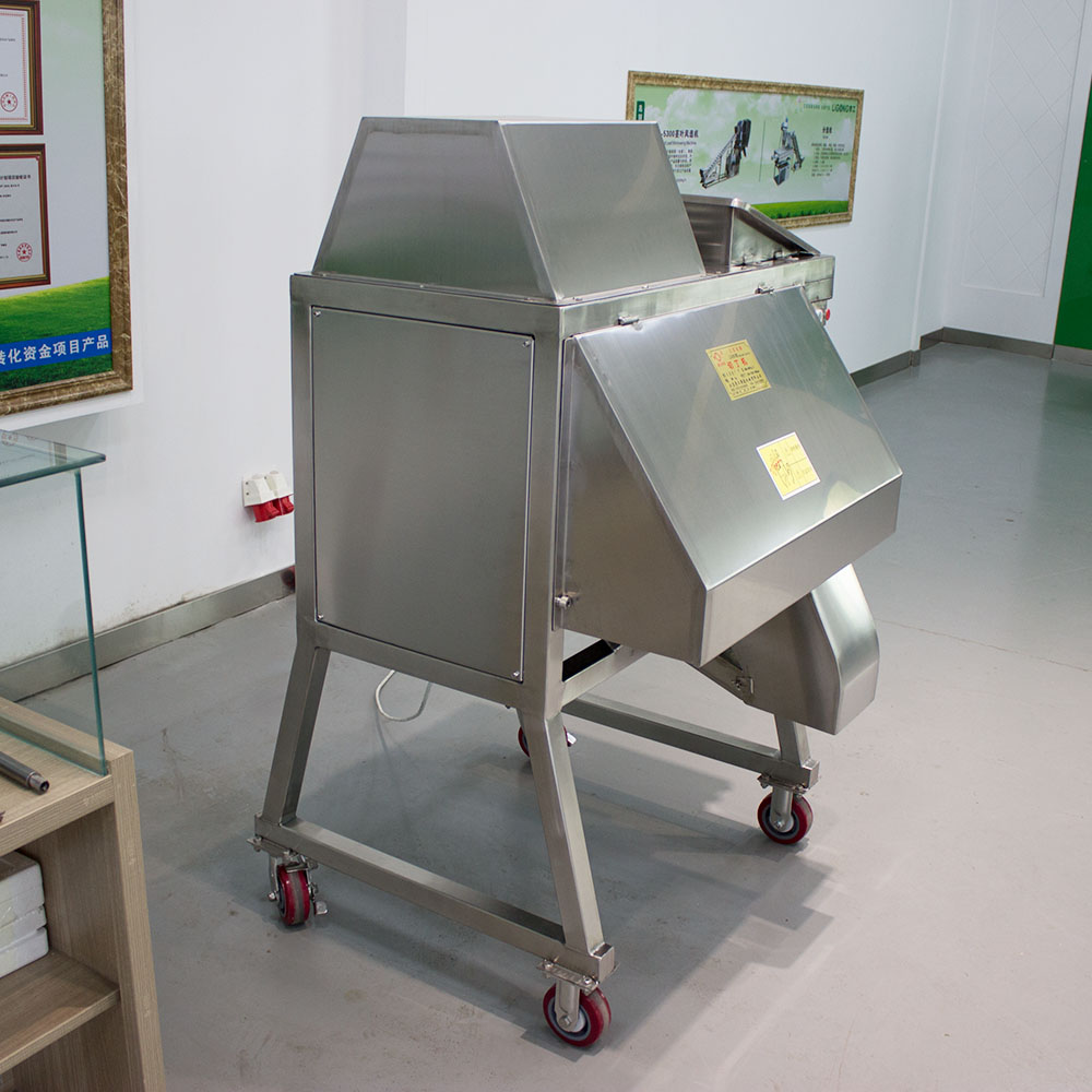
LG-350 Fruit And Vegetable Dicing Machine


Technical Parameters
a.Propeller diameter:350 mm
b.Motor : Y112M-44KW
c.Capacity: 1000-2000kg/h
d.Weight: 350kg
d.Dimensions: 1100x 1100 x1600mm ( length * width * height )
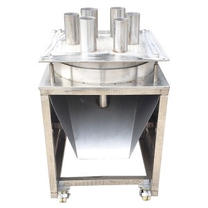
e. Feed inlet: inlet height from the ground1310mm inlet area of 450× 360mm
f. Discharging port: outlet height from the ground490mm export area of 195× 60mm
Working principle
From raw materials into the hopper into the rotation of the propeller, the product under the action
of centrifugal force, close to the inner side of the outer shell, with the propeller blades through the slicing
knife, and along the slicing knife from the housing front adjustable door to move out, slice thickness by
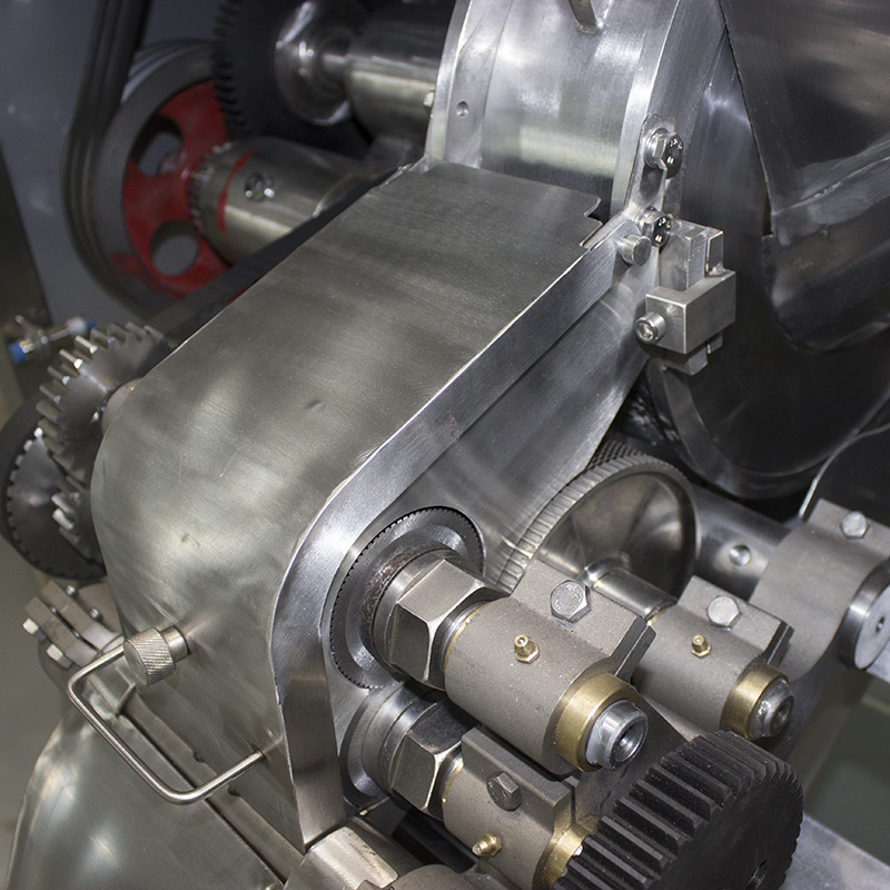
the door end of slice blade openings is determined. Slice by slice guide into the rotation of the feeding roller, feeding roller and the relative rotation of
the auxiliary feed shaft, will be sent to the disk slice cutter shaft, products are cut into strips, then
directly to the rotation of the knife, cut its square, rectangle or other preset dimension. Features: slice through a pair of feed rollers, not block into the cut, process.
Cutting size
Adjust the opening of the housing door, the spacing of the disc cutter, and replace the knife
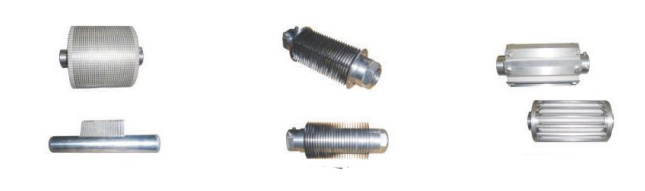
assembly. It can be cut in a variety of sizes. 1. Remove the disc knife assembly, auxiliary feeding assembly and strip knife assembly, adjust the
opening of the shell door, and it can cut 1.6 ~ 11mm slice. 2. Install the disk knife assembly, auxiliary feeding assembly, without a knife assembly, can cut strip, wire, block shape. 3. Install all the cutters
Can cut: 3 * 3 * 3, 3.5 * 3.5 * 3.5, 4 * 4 * 4, 5 * 5 * 5, 6 * 6 * 6, 7 * 7 * 7, 8 x 8 x 8, 10 * 10 * 10 tee
Can also be cut: 3 * 3 * (1.6 ~ 11), 3.5 * 3.5 * (1.6 ~ 11), 4 x 4 x (1.6 ~ 11), 5 * 5 * (1.6 ~ 11), 6 x6 x (1.6 ~ 11), 7 * 7 * 1.6 ~ (11), 8 x 8 x (1.6 ~ 11), 10 * 10 * (1.6 ~ 11)
As well as long 19, 25, 30 or free length of silk strips, can also be combined to cut the thickness of less
than 10 required cubes. 4. According to the tool combination can cut the thickness of different square shape, rectangular strip, strip length can be 15, 20, 25, 30 or free length. 5. Remove the knife assembly, and the material can be cut into free long wire strips. 6. Cut 3×3, 6×6 pieces, sharing the same specification (3) auxiliary feeding assembly, feeding drum
and comb tooth assembly. Cutting 4×4, 8×8 pieces, sharing the same specification (4) auxiliary feed assembly, feed roller and
comb tooth assembly;
Cutting 5×5, 10×10 pieces, sharing the same specification (5) auxiliary feed assembly, feed roller and
comb assembly.
Install the operating
1.The installation position of the equipment should be so that the equipment is stable and has enough
space for easy cleaning and maintenance.
2. Connect the power so that the propeller rotates counterclockwise when viewed from the feed port
and is properly grounded.
3. Before starting the device, it is necessary to ensure that all foreign bodies and products in the
feeding area have been removed, and the hand disc is synchronized with the belt wheel to ensure
that there are no foreign bodies in the slicing device.
4. Start the motor, make it reach full speed working state, stable and uniform from the feed port
feeding.
Note:
(1) do not let foreign objects such as tools, stones, bottles and other hardware into the feeding area, so as not to damage the cutting machine parts.
(2) Do not continue to overfeed, so as not to overload the motor, feed port congestion or the cutting
tool stuck, affecting the quality of the product.
(3) Do not put your hand into the feed mouth, so as not to cut off the arm.
(4) When the equipment is in operation, the cover plate or protective plate shall not be removed to
avoid serious injury.
(5) The blunt blade must be sharpened before it can be used again.
Maintenance
The machine contains sharp cutters, rotating parts and high voltage power supply. When changing cutting specifications and maintaining equipment, the power supply must be disconnected and locked
first. The cover plate and protective plate can be removed after visually confirming that the equipment has been completely stopped, otherwise serious injury may be caused.
(A) daily maintenance
1. Remove cover plate and guard plate for maintenance of all parts of equipment.
1) Remove the cover plate, protective plate and section guide cover to maintain the dicing assembly
and lubricate the machine.
2) Disassemble the feed hopper to maintain the slicing device.
3) Disassemble the slice guard plate to maintain the dicing component and driving component.
2. Cleaning: disconnect and lock the power supply, remove all cover plates, and clean thoroughly.
3. Lubrication: 8 copper lining lubrication points of this machine are equipped with marble copper oil
nozzles (as shown in the figure). Food grease must be added once for 4 ~ 6 hours of operation, and the
operation must be kept flexible. Random fittings for refueling: ordinary 400g pressure bar type butter
gun. The gear parts are often lubricated.
(B) Maintenance of key parts and components
1. Disassembly, inspection, cleaning and installation of dicing device.
1) remove
a. Disconnect and lock the power supply, remove the front panel, blanking groove, section guide
cover, protective plate, and remove the synchronous belt.
b. Remove the blade assembly: loosen the fixing screw on the blade shaft, hold the blade assembly, and pull out the spindle and gear.
c. Disassemble the disc cutter shaft: remove the synchronous belt, loosen the fixing screws of the nylon gear, remove the strip cutter transmission gear, loosen the fixing screws of the knife shaft, hold the disc cutter assembly with one hand, and take out the disc cutter shaft with the other.
d. Remove the auxiliary feed shaft: loosen the fixing screw of the auxiliary feed shaft, hold the
auxiliary feed shaft assembly with one hand, and pull out the auxiliary feed shaft with the
other. 2) Cleaning inspection:
Clean thoroughly, check journal and copper lining for wear, and remove comb teeth
and feed barrel if necessary. 3) Reassemble:
A. When installing the shaft, the shaft must be able to be pushed in and rotated freely. B. Install the feed drum: place the feed drum in the center of the two side supports, and
the gap between one end and the end face of the copper liner is about 0.1mm. Push the
feed drum shaft and tighten the fixing screws (note that the two fixing screws should fall
into the pit of the shaft).
C. Install the disc cutter assembly: push the disc cutter shaft part into the side bracket, position the disc cutter assembly between the two copper linings, the disc blade is placed
in the center of the feed cylinder groove, and then push the shaft in, so that the gap between one end and the end face of the copper liner is about 0.1mm, tighten the two fixed
screws (pay attention to fall in the pit of the shaft). D. install auxiliary feed shaft assembly: the side of the auxiliary feed shaft parts into
scaffolds, the auxiliary feed assembly in between the two brass, make the carbon blade for auxiliary feed between disc blade, and then into the auxiliary feed axis, the side away from
the brass side clearance is about 0.1 mm, the two fixed screw (be careful to fall in the pit shaft). e. Install the comb: Install the comb of the comb shaft in the central position between the disc
blade, turn the comb shaft upward until the comb tip touches the spacer block of the disc cutter assembly, and tighten the side bracket cap with moderate strength. f. Install the cutter assembly: push the cutter part into the side bracket, place the cutter assembly between the two copper bushing, then mount the cutter shaft so that the gear is aligned with the disc cutter shaft gear. The clearance between the end of the cutter and the end face of the copper bushing is about 0.25mm, and tighten the two fixing screws (pay attention to the pit
of the shaft).
2. Assembly of disc cutter assembly, auxiliary feed assembly and blade assembly
1) the disc cutter assembly on the cutter holder to mount a gasket at the beginning, then alternate install disc blade (knife blade should be facing the same direction) and gasket (different blanking specifications, beginning a spacer thickness between gasket and a knife and knife is
differ, special attention should be paid to when removing assembly, gaskets according to the original order in place, and not disorder), and finally tighten the clamp nut.
2) auxiliary feed assembly: on the cutter holder to mount a beginning after the gasket (blanking different specifications, the beginning gasket thickness is differ), fitted with a disc knife, and then mount gasket and complementary feeding blade, alternately on the shaft of the last one is
for disc blade and ending gasket (pictured), when tighten nut, to keep the carbon blade for auxiliary feed six teeth alignment.
3) knife assembly: 3, 3.5, 4, 5, 6, 7 mm butyl piece of a knife is through the two locating ring fixed on the tool carrier, when installation will first locating ring at the end of the screw tight, make it close to the article in the knife rest, and then carefully push the knife into the slot, mount a
second ring, gradually alternately tighten nut, but not too much. The installation of 8 ~ 10mm cutters must make the cutters tightly located at the bottom of the knife seat to ensure that the 0.038mm feeler can not be inserted into the gap behind the knife.